Projects
I have custom-designed printed circuit boards to implement two things:
- A dual CI-V to RS232 interface (also capable of interfacing Yaesu) which measures 1½ inches square and runs from a single 9 volt wall transformer. Cost to construct, including new parts from Digi-Key is approximately 20 dollars excluding housing
- A dual band-decoder intended to convert LPT band output (typical of many logging programs) to 9 discrete open-collector band signals. There are also provisions for pull-ups to operate LED's to indicate the various bands. This all operates from a single 12 VDC wall transformer with sufficient current ratings to support the various relays in filters and antennas.
PC boards were designed using the software from ExpressPCB. This is really great stuff. After designing both boards, I read the ExpressPCB documentation and realized that it would be much cheaper to combine the two boards into a single board and cut the board myself. This is because of the setup charge at ExpressPCB which is much larger than the area charge.
I bread boarded the CI-V decoder and the band decoder before designing the boards. The band decoder is similar in function to the TopTen Band Decoder with some refinements as well as extending the concept to packaging two decoders on a single board with common power. One neat feature of the TopTen board is the use of packaged multiple Darlington transistor pairs. Not only does this decrease size and complexity, but it turns out that the IC also includes diodes to handle the back emf from relays, saving even more board space.
I carefully drew the diagram for the CI-V board using Microsoft Visio. The program is a pain in the neck to use, but does produce nice results. I then checked the board design against the diagram to insure accuracy. As a result, there were no mistakes on the Dual CI-V board.
In the case of the dual band decoder, I had a diagram of the bread boarded decoder. Unfortunately I made a number of changes during the board layout to facilitate better layout. I never diagramed or checked the changes. As is typical when one becomes too self-confident, mistakes were made. They were minor, consisting of three traces that had to be cut and routed one IC pad to the side and one missing trace. No big deal -- but annoying. Will check better next time!
I have integrated the two boards, the W5XD keyer board and a homebrew LED display into a cabinet and have been using the resulting device in SO2R contest operation since the June, 2000.
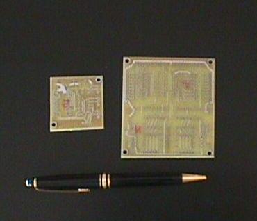 Dual CI-V board on left, dual band-decoder
on right.
Dual CI-V board on left, dual band-decoder
on right.
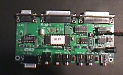
 This is the completed
band decoder board. The two 4 bit data inputs from the W5XD contest keyer
are on the right. The large top and bottom Molex connectors are for the
LED band indicators arrays. The two 11 pin Molex on the left supply +12,
GND, and 9 band contact closures for use primarily with automatic band pass
filters, although they could be used to select antenna or for other functions.
This is the completed
band decoder board. The two 4 bit data inputs from the W5XD contest keyer
are on the right. The large top and bottom Molex connectors are for the
LED band indicators arrays. The two 11 pin Molex on the left supply +12,
GND, and 9 band contact closures for use primarily with automatic band pass
filters, although they could be used to select antenna or for other functions.
 This is a completed W5XD
contest keyer. The keyer works in conjunction with the Writelog
software marketed by K5DJ. It is connected to one of the rig control
serial interfaces and provides control and keying functions including: CW
keying, band decoding for TopTen or other band decoder, head phone selection,
and PTT. It is of particular interest to Windows NT and Windows 2000 users as many of these
functions are only available via LPT interface, which is not supported using
Writelog under NT or Windows 2000. Since it also includes CW keying, the keying is no
longer sensitive to multitask delays on the computer. One note, the
standard board includes board-mounted connectors for basically all
functions. This is very inconvenient for packaging and the second board
now being assembled will actually be used for the integrated control box and
will omit these connectors.
This is a completed W5XD
contest keyer. The keyer works in conjunction with the Writelog
software marketed by K5DJ. It is connected to one of the rig control
serial interfaces and provides control and keying functions including: CW
keying, band decoding for TopTen or other band decoder, head phone selection,
and PTT. It is of particular interest to Windows NT and Windows 2000 users as many of these
functions are only available via LPT interface, which is not supported using
Writelog under NT or Windows 2000. Since it also includes CW keying, the keying is no
longer sensitive to multitask delays on the computer. One note, the
standard board includes board-mounted connectors for basically all
functions. This is very inconvenient for packaging and the second board
now being assembled will actually be used for the integrated control box and
will omit these connectors.
Visitor number