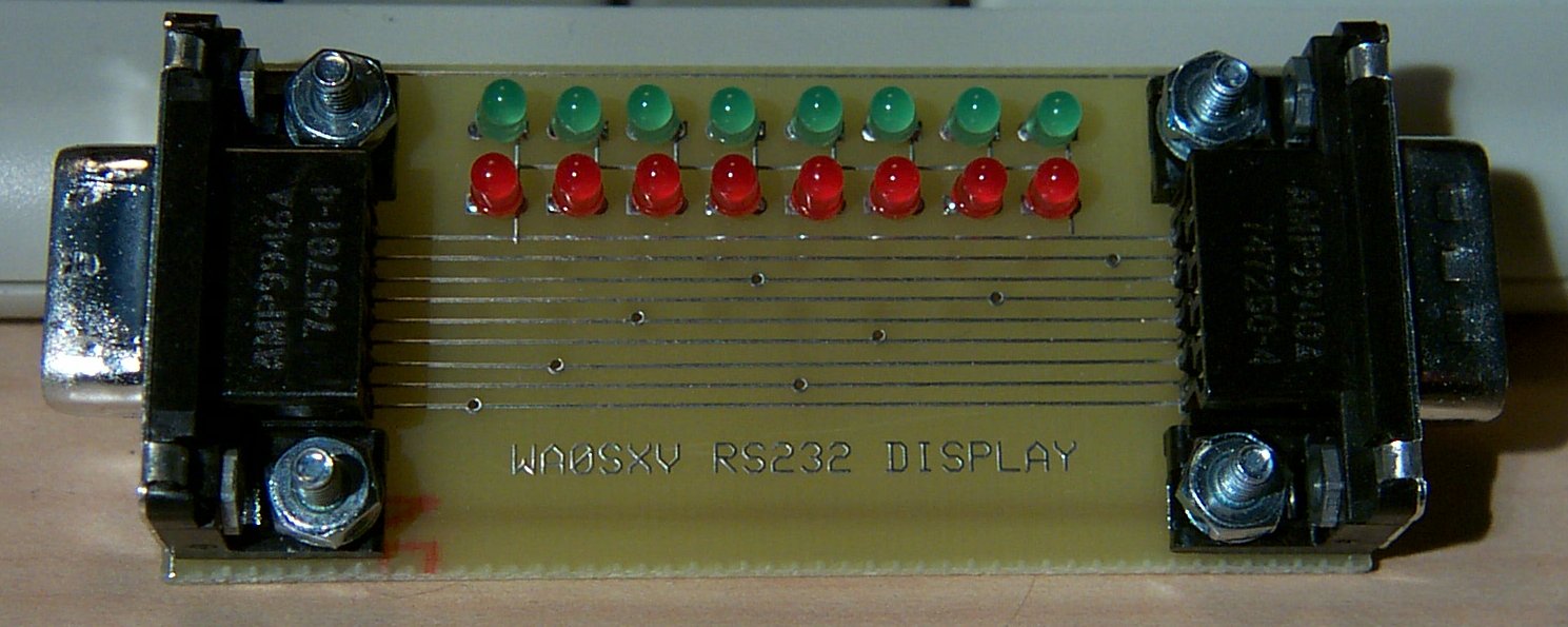
Javascript DHTML Drop Down Menu Powered by dhtml-menu-builder.com

RS232 Display Board

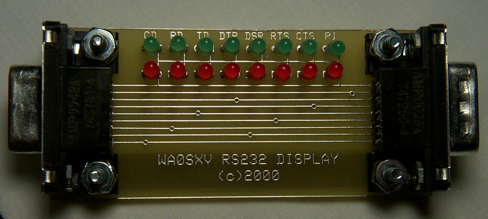
While trying to debug some CI-V to RS232 interfaces and other ham projects that connected to the serial port on the computer, I grew frustrated trying to determine whether they were even talking to the serial port.  After one particularly annoying session trying to get my PTC-II downloaded from my laptop, only to discover that the serial port had to have the modem leads turned on, I decided to buy a signal display for RS232.  Off to Radio Shack.

Unfortunately, I didn't find anything suitable.  Since I've started designing my own PC boards recently and since I wanted to play with surface-mount technology (smt), I decided to build a simple RS232 signal display board to show all signals.

Note:  Click on the picture to receive a magnified view.

The board is trivial to use.  You merely insert it between the RS232 cable and either the remote device or the serial port as appropriate.  Each of the 8 valid RS232 lines has two LED's -- a red and a green.  If the red is lighted, then the RS232 signal is currently a negative voltage (logic 0).  If the green is lighted, it is a positive voltage (logic 1).  If neither lights then the line is not a valid RS232 line.  If they both light and it is not at reduced brilliance and the signal is not changing state, then one of the LED's was mounted incorrectly!
SMT was used on the reverse side of the board for the dropping resistors.  This really wasn't necessary -- normal resistors could have been used -- but it was fun.  The 1206 (.12" by .06") resistors were used.  They were soldered using normal 63/37 solder, a pair of pointed tweezers, and a Weller temperature-controlled iron with a 1/32" tip, and a readily-available magnifying lamp (Home Depot has them).  Actually -- I don't use the magnifying lamp any more -- it just isn't that difficult even at age 51 to solder this.  I also purchased a flux pen and brushed across each of the pads with flux before starting.  The process used is to hold the resistor in place using the tweezers and then very lightly touch one of the sides with the soldering iron.  The tinning on the board is adequate to temporarily hold the part in place.  You then put a touch of solder on the opposite pin.  When it cools put the proper touch of solder on the original pin.  After you're finished, the entire board should be cleaned with flux remover for aesthetic reasons.


(click on image for full size view)

This is the new version.  In addition to cleaning up some pc board glitches, it includes the designations for the various RS232 lines.

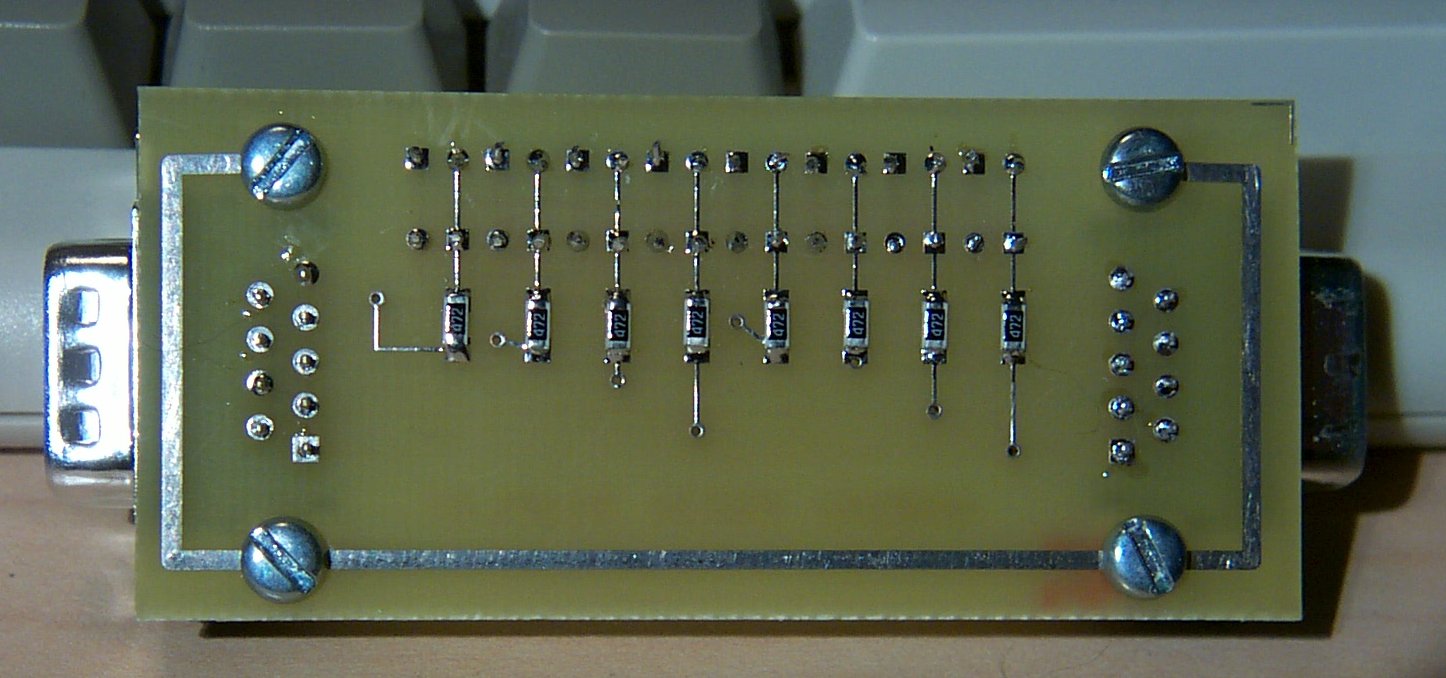
Components are off the shelf from DigiKey and cost around ten dollars.

Constructions details are here.


Visitor number