CI-V boards and comments
FOR SALE: I have several of the smt boards without components. These boards are $10 each shipped US. Payment by PayPal. Contact me here.
I have designed and built a dual CI-V to RS232 interface (also capable of interfacing Yaesu) which measures 1½ inches square and runs from a single 9 volt wall transformer. Cost to construct, including new parts from Digi-Key is approximately 20 dollars excluding housing.
Why not use the CT-17? Well, I had one and it worked well. It adheres more to proper design than most of the ham designs and has extensive filtering. It uses the Maxim chip so it generates proper levels. I just wanted greater density and wanted to experiment. In addition, the CT-17 is much more expensive and does not use an open-collector output to control the CI-V line which is a violation of the TTL standards.
Why dual?
Well, all the parts (except a resistor and three capacitors) were already there and therefore dual was essentially free. And I needed two converters at each of my stations and wanted to cut down the number of wall transformers and goodies dangling around the station.
In working on these projects, I spent some time looking at the CI-V bus and the resulting RS232 output for Icom remote control. Briefly, watch out if you're building your own CI-V interface. The QST February, 1993 article on the interface is excellent, but several parts values are incorrect. In particular, using .01 µf bypass capacitors on the CI-V line results in unacceptably slow rise times at 9600 and 19200 baud. Icom uses 100 pf, which is fine in combination with the inductors they use. I'm currently using 470 pf. Whatever -- don't use the .01 µf on the CI-V bus. The RS232 lines seem to have enough power behind them to survive the .01 on them. In addition, the various 10 µf capacitors in that article can be either 1 µf or .1 µf depending on whether a normal or "A" version of the MAX232 chip is used.
Also of interest is the fact that, although they work, solutions involving
the Icom OPC-478 cable and variants which use two or three transistors, use the
serial interface power, and don't
necessarily generate a negative voltage may actually violate the RS232 signal standards.
As such, they may be vulnerable to numerous maladies including lack of noise
tolerance and possible rate and content related errors. The MAX2xx line of
chips actually include voltage doublers and generators of negative voltage.
Only one of the discrete component designs I've seen actually does this.
Compliance with these standards can be measured with a voltmeter or examined
visually using an RS232 signal display.
Another drawback of the port-powered interfaces is that they simply may not work
on many laptops due to the lack of necessary control signals on the serial port.
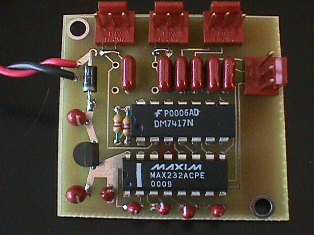 This is the dual CI-V/Yaesu
board up
close. Dimensions are 1½ x 1½. It is actually square.
The dimensional distortions are the result of camera angle and a sloppy cutting
job on my part. the unusued pads are bypass capacitors not needed for
the Icom interface. This particular picture was taken when the CI-V bypass
capacitors were still .01 µf. These are the two capacitors to the upper
left. These are now 470 pf. The entire assembly is powered by a 9v,
100 ma wall transformer available from Digi-Key for around 5 dollars.
This is the dual CI-V/Yaesu
board up
close. Dimensions are 1½ x 1½. It is actually square.
The dimensional distortions are the result of camera angle and a sloppy cutting
job on my part. the unusued pads are bypass capacitors not needed for
the Icom interface. This particular picture was taken when the CI-V bypass
capacitors were still .01 µf. These are the two capacitors to the upper
left. These are now 470 pf. The entire assembly is powered by a 9v,
100 ma wall transformer available from Digi-Key for around 5 dollars.
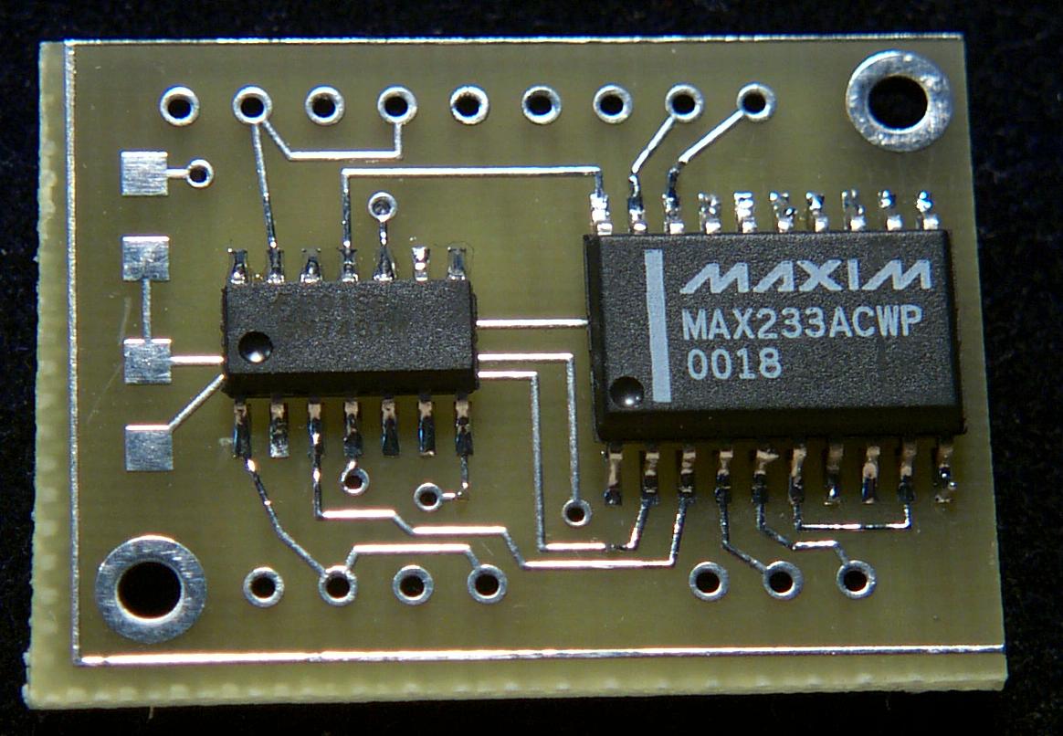
A Surface Mount Technology (SMT) version of the dual board was designed, built,
and tested. It measures 9/10 x
1 1/4. In fact, it is almost too small as it is difficult to attach all of
the requisite wires to it.
|
|
This is the top view of the smt-based dual CI-V interface. It uses the Maxim 233 chip which minimizes component count -- there are four less tantalum capacitors. Unfortunately, at the same time it is significantly more expensive than the cheaper MAX232. A final production design would use the 232. The unused pads on the left are for 4.7k ohm pullup resistors that I did not mount on this board. Finshed boards should use the resistors. |
|
|
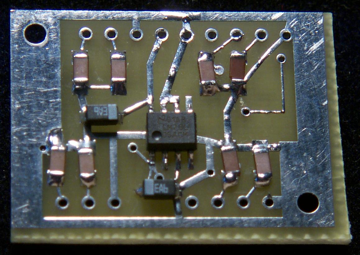
This is the back and it shows why I've finally decided to not use smt unless absolutely necessary. Those ceramic chip capacitors are REALLY small. Disaster struck when the four on the right were inadvertently installed at right angles to the correct installation. Removal made a mess as I was, for some reason, trying to save the caps. Foolish move -- they are only twelve cents each! The board pad that I lifted in the process was somewhat more precious! Anyway -- it works and will be in a box so who cares about ugly? |
I'm currently using the smt version to interface PTT and FSK for the primary radio in my SO2R layout in New Mexico. A bit of overkill but works great.
Construction information for the smt version is here.
By the way -- there is lots of good information on CI-V available at DF4OR's CI-V page.
Visitor number